Development concept
Purpose of development
The purpose of developing the RC213V-S is to enable each rider of this machine that they can ride on public roads, not a racing machine, to experience for themselves why MotoGP riders racing the RC213V can concentrate on emerging victorious amid the ultimate battles. The RC213V is Honda’s machine that competes in MotoGP races.
In developing the RC213V-S, this RC213V was used as the base model. The RC213V, launched in 2012 to compete in MotoGP races, is a machine with a top speed of more than 300 km/h. For two seasons in a row, 2013 and 2014, Honda has won the three MotoGP championship titles of the Riders’ (Marc Márquez), Constructors’ (Honda) and Team Championships (Repsol Honda Team) with the RC213V.
Developed with the purpose of letting its rider win MotoGP races, the RC213V comes with a maneuvering feel of superior quality. Not only racing riders but also ordinary sport motorcycle riders can fully enjoy the fun-to-ride qualities the rider feels by maneuvering the RC213V, and even when riding at a slow speed, the rider can savor these qualities. Whereas the RC213V finishes its role after each season of races, the RC213V-S has been developed as a model you can simply continue riding.
Development policy
Rather than trying to replicate the power performance of the RC213V, our development policy focused on recreating the whole packaging as a complete vehicle, and the resulting maneuvering feel. With riding on public roads as the premise, we judged it as rather inappropriate to replicate the power performance of the RC213V.
In developing the RC213V-S, we developed the Sports Kit assuming the possibility of riding the model on a closed circuit such as a racing circuit. When riding on a closed circuit, the rider can remove the lights that have been installed for riding on public roads and install the optional Sports Kit, which enables replicating the maneuvering feel in speed ranges closer to the world of the RC213V.
Organizational structure for development
The RC211V, which was launched for racing in MotoGP in 2002, was developed by Asaka R&D Center (predecessor of the current Motorcycle R&D Center, or HGA) and handed over to Honda Racing Corporation (HRC) for eventual entry in actual races. In contrast, the RC213V developed by HRC was used as the base vehicle for development of the RC213V-S, and a development team in the Motorcycle R&D Center, centering around members with past development experience on the RC211V and RC212V, worked on developing the RC213V-S.
The models for development and the associates in charge of development constantly change places between HGA and HRC. Such drastic changes in work requirements and the workplace environment is an effective form of training—this is Honda’s way of fostering talent and promoting the evolution of products by drawing on these precious experiences for associates in the development of production models.
Vehicle overview
The RC213V-S was created in essence by making it possible for the RC213V to run on public roads.
With the RC213V, “ease of maneuvering” was positioned as the “necessary means for winning races,” and to improve the running performance to extreme levels to this end, thorough measures were applied to ensure mass concentration and reduced friction. The two key aspects in manufacturing for achieving these goals that set it apart from ordinary mass production models with substantial differences are “light weight and machining precision of the components” and “superior expert skills required in manufacturing.” The RC213V-S adopts these manufacturing characteristics and is also equipped with the control technologies used on the RC213V.
As a racing machine, the RC213V consists of the necessary parts for winning races, based on the idea of changing specifications according to the rider and course. To ensure that the RC213V-S is capable of running on public roads, the minimal amount of necessary changes and additions were made compared to the RC213V, with the following component changes and additions made as a result.
- Based on the idea of servicing the parts in a realistic maintenance environment, a switch was made in the pneumatic valve to a coil spring system, while inheriting the camshaft gear train structure. The seamless transmission was also changed to a conventional system. These specifications are the same as those for the RCV1000R, an open category racing machine sold on the market.
- New components have been added for compliance with the laws and regulations for riding on public roads, without changing the basic layout of the RC213V. These are the lights, rearview mirrors, speedometer, a muffler with a catalyst, the license plate holders, and the horn.
- To ensure practical qualities when riding on public roads, changes were made in specifications for the tires, brake discs and pads, and the steering angle was changed. The Honda Smart Key, a starter motor, and a side stand have also been added, among other features.
The control technologies incorporated into the RC213V-S have been adopted for supporting the riding styles of a wide range of rider types operating in various situations. These technologies help the rider concentrate more on machine control and sustaining their concentration.
To recreate the RC213V’s maneuvering feel, the materials, surface treatment processes, and manufacturing methods different from those for ordinary mass-produced vehicles on the market are used, in order to ensure the necessary strength and rigidity along with weight reduction, similar to the RC213V. The idea of using both machining and manual procedures to process individual parts has been applied, for incorporating dimensional accuracy at the RC213V level into the design. As for the manufacturing approach, an exclusive workshop has been set up inside Kumamoto Factory, where full-time experts who received special training are in charge of manufacturing the RC213V-S. For fully bringing out the intended functions and performance of the RC213V-S, it is essential not only to use a full amount of manufacturing time necessary until completion of each of the components, such as the cowling and frame, but also to rely on manual work for fastening the bolts and nuts in assembly according to specified torques. All these conditions mean a production pace of one unit per day.
The RC213V-S also requires maintenance processes different from those for Honda’s ordinary mass-produced models on the market. Because high-level maintenance techniques and skills are required for all inspections and maintenance procedures, except for pre-riding checks, they have to be carried out at designated dealers with tools designed exclusively for the RC213V-S. Also, because the specifications of the RC213V have been adopted for the frame body and the like, which use anodized aluminum and other materials without anti-corrosion treatment, vehicle storage is based on the idea of keeping the machine indoors under sufficiently controlled conditions.
CBU packaging overview
The complete vehicle packaging for the RC213V has a thorough focus on concentration of mass for enhancing running performance to the extreme.
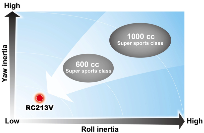
The moment of inertia considerably affects the running performance of the complete vehicle, not only for racing machines but also for super sports models, which makes it crucial to reduce the moment of inertia through mass concentration. Weight and vehicle class have the greatest effect on the inertial mass of a complete vehicle, but making parts that are relatively far from the center of gravity more lightweight and placing them closer to the center of gravity also helps reduce inertial mass.
To advance mass concentration, thorough measures were taken to make the 90-degree V4 1000cc engine of the RC213V as compact as possible, which enable its installation on frame dimensions equivalent to those of the 800cc RC212V. To ensure body dimensions that are capable of withstanding the high power, a longer wheelbase than common super sports models are adopted for the RC213V, while weight reduction has been achieved for suspension parts that are relatively far from the center of gravity. As a result, the RC213V has a complete vehicle inertial mass lower than that of 600cc class super sports models mass-produced and available on the market, while achieving the targeted running performance.
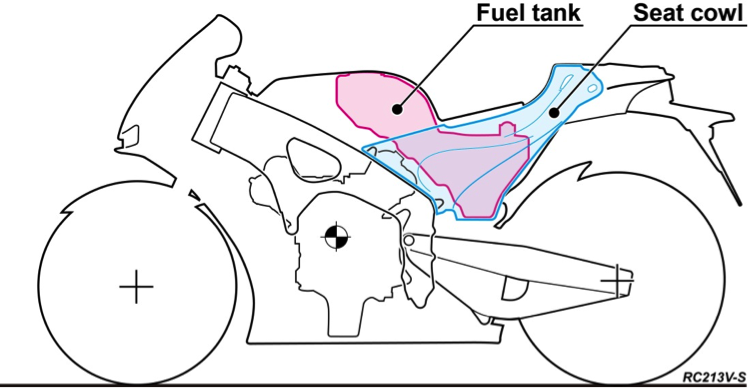
Placing the fuel tank near the center of gravity of the complete vehicle has also contributed to reducing complete vehicle inertial mass for the RC213V. Changes in the center of gravity due to the gradual decrease in carried fuel have also been minimized, restraining any change in vehicle body behavior from the start to finish of any race.
The RC213V-S inherits this complete vehicle packaging from the RC213V, from the materials to manufacturing methods of the vehicle components. Given the need for riding on public roads, a larger battery is installed on the RC213V-S, with electrical components also added. But even for these changes and additions, relevant components have been placed near the center of gravity, which has helped curb the complete vehicle inertial mass and achieve the targeted running performance.
When removing the lights installed for riding on public roads and installing the Sports Kit on the RC213V-S to create the conditions exclusively for circuit riding, the body inertial mass comes extremely close to the level equivalent to that of the RC213V.
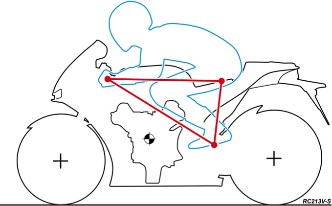
Riding position diagram
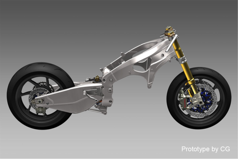
Parts configuration diagram

Image diagram of Yaw inertia and Roll inertia
Frame
Frame body
The aluminum frame body of the RC213V has high torsional rigidity for transmitting high power to the road surface. Increasing torsional rigidity usually tends to increase frame body weight, so for the RC213V, the necessary rigidity has been provided only to the parts requiring it, while thin plates are used for those areas with smaller contribution to rigidity, thereby achieving a lightweight frame body overall.
Also, each and every part comprising the frame body of the RC213V undergoes its final fitting through a manual process including TIG welding by full-time experts. The method necessitates a large volume of welding work, but ensures high precision and welding quality without fail. The materials and manufacturing methods used for the RC213V have been adopted as much as possible for the RC213V-S.
Furthermore, to fasten individual parts that make up the body of the RC213V-S, machined bolts made of titanium alloy similar to those for the RC213V are used, contributing to weight reduction. For stabilizing the axial force during assembly, application of molybdenum grease is specified, and all bolts are manually fastened without using an impact wrench, at specified torques that are different from those for ordinary steel bolts.
Frame body diagram
Head pipe adjustable structure
The RC213V uses a head pipe with eccentric collars press-fit to enable changing the caster angle and the pipe position according to racing course and characteristics of the rider. Recesses are created on the upper and lower ends of the head pipe through fine blanking to achieve smooth, high-precision machined surfaces. By employing a design in which eccentric collars are press-fit in the recesses and the stem pipe passes through the eccentric collars, the rider can change the vehicle body geometry without having to replace the frame. The design structure also allows for adjustment of the steering angle by the handlebar stopper. These RC213V settings are also adopted for the RC213V-S. (Eccentric collars for adjustment is not an available setting.)
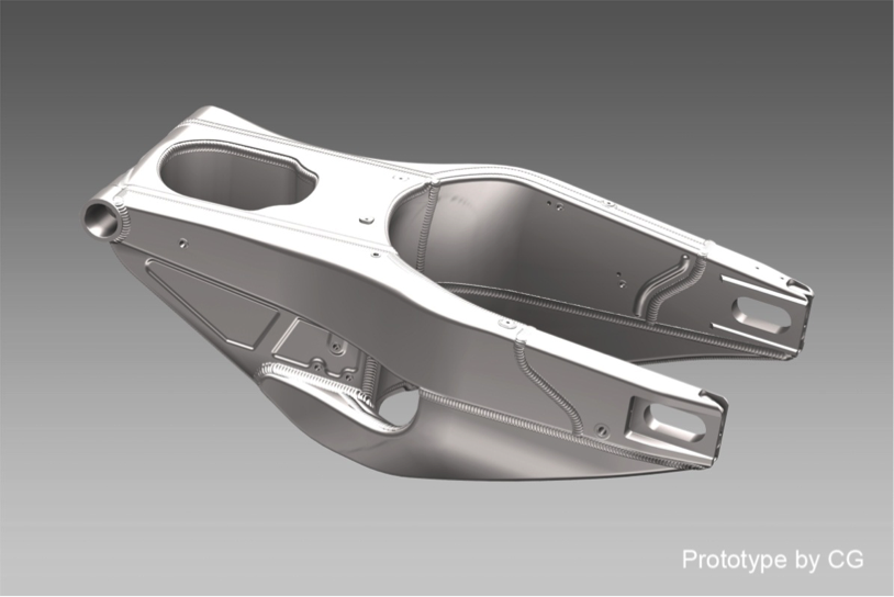
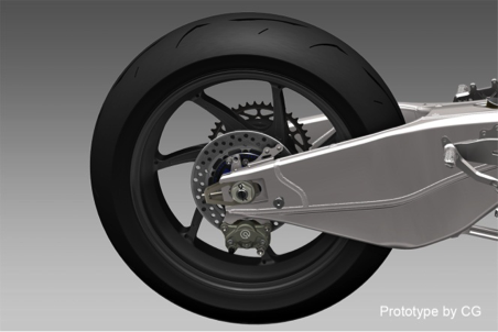
Swing arms
To achieve the fuel tank shape with its purpose of reducing the moment of inertia for the vehicle body, the RC213V uses triangular swing arms placed lower. The balance between torsional rigidity and transverse stiffness has been optimized for the RC213V, in order to achieve the maneuverability needed in MotoGP racing. The swing arms are made of press-formed aluminum, and end pieces and cross-body parts are created wholly by machining aluminum materials, and with manufacturing through TIG welding by full-time experts, both excellent maneuverability and weight reduction have been accomplished. These configurations and manufacturing methods for the RC213V are incorporated without change into the RC213V-S.
Swing arm diagram
Fuel tank
The fuel tank of the RC213V is located inside the seat cowl near the vehicle’s center of gravity, which minimizes changes in the center of gravity resulting from a gradual change in the loaded fuel volume, and thus greatly restrains any changes in vehicle body behavior.
The RC213V-S comes with a fuel tank of the same shape as that of RC213V, while also using the same configuration, position and manufacturing method as the RC213V. After workers manually fit the end faces of the press-formed aluminum sheets, full-time experts manufacture the tank with TIG welding, ensuring high precision and welding quality.
Fuel tank layout drawing
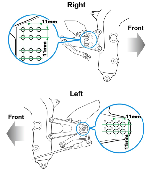
Step position adjustable structure
RC213V-S adopts the step position adjustable structure of the RC213V. By making the step adjustable to three lateral positions and two vertical positions, each set 11 mm apart, a high degree of freedom has been secured for the riding position, which positively affects the ease of maneuvering the vehicle.
Because the RC213V is based on the concept of riding on racing circuits, setting deep banking angles is necessary to prevent any part of the vehicle from touching the ground. The RC213V-S inherits the step and pedal structures of the RC213V, ensuring deeper banking angles than for mass-produced models on the market. To achieve a more secure gear-shifting touch, bearings are incorporated into the shaft bushes of the gear change pedal, just as for the RC213V, thus minimizing looseness of the pedal.
Step position adjustable structure
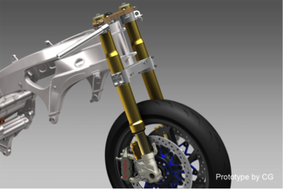
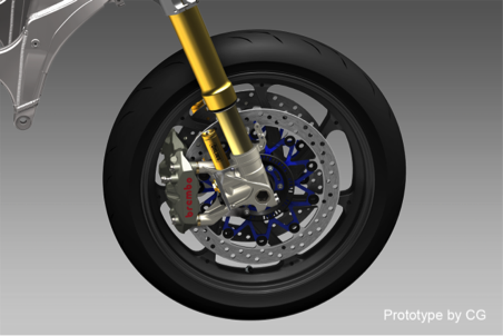
Front forks
The RC213V-S uses front forks made by Ohlins Racing AB, just as on the RC213V. The TTX25 pressurizing front forks contribute to the excellent stability in cornering and the enhanced maneuvering feel for the vehicle body. Dust seals have also been added in consideration of the bike’s use on public roads.
Front fork diagram
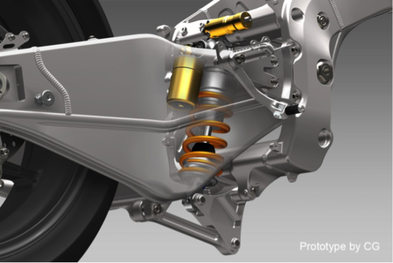
Rear suspension
The rear suspension of the RC213V achieves excellent road-gripping performance in cornering and a high absorption performance for any gaps in road surfaces, and these characteristics have been very much inherited by the RC213V-S.
For the rear cushion, the RC213V-S uses a product made by Ohlins Racing AB, just as on the RC213V. Based on the GP specifications TTX36, a new preload adjuster designed exclusively for the RC213V-S is mounted on the backside, enabling adjustments matching the riding conditions and each rider’s preference.
Swing arm and rear suspension diagram
Brakes
In dry conditions, the RC213V uses carbon brake discs, but for the RC213V-S, the stainless discs of the RC213V mainly used in rain have formed the basis of brake design. To ensure stable performance when riding on public roads and racing circuits alike, the thickness of the stainless discs has been set at 5.5 mm. Floating discs are also used for both the front and rear brakes, and similarly to the RC213V, the disc hubs have been wholly machined from aluminum materials.
The RC213V-S uses the same Brembo S.p.A. components used on the RC213V for its front and rear brake calipers, front master cylinder, and clutch master cylinder. The same tiltable brake and clutch levers as on the RC213V are also used. For the front brake lever, a brake lever remote control unit can be attached for adjusting the play in the lever, as part of the optional Sports Kit. For both the brake hose and clutch hose, stainless mesh hose and stainless end fittings are used.
Tires, Wheels
For wheels of the RC213V-S, forged magnesium wheels made by Marchesini are used to share the same design as the RC213V, with 17-inch wheels used for the RC213V-S. For tires, the RC213V-S has adopted the RS10 made by Bridgestone Corporation, which are commercially available.
Front and rear tire and wheel diagram
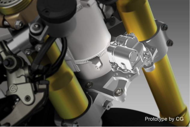
Steering damper
The rotary steering damper is the same as that on RC213V and installed ahead of the head pipe—the same position as on the RC213V. For the damper body, the RC213V-S uses the same part as for the RCV1000R, which is an open category racing machine sold on the market. Damping characteristics are adjustable by the rider according to wide-ranging conditions, from riding on public roads to racing circuit riding.
Steering damper diagram
Reinforced chains
The RC213V-S has adopted chains made by RK JAPAN Co., Ltd., just as on the RC213V, with “520 reinforced chains” used.
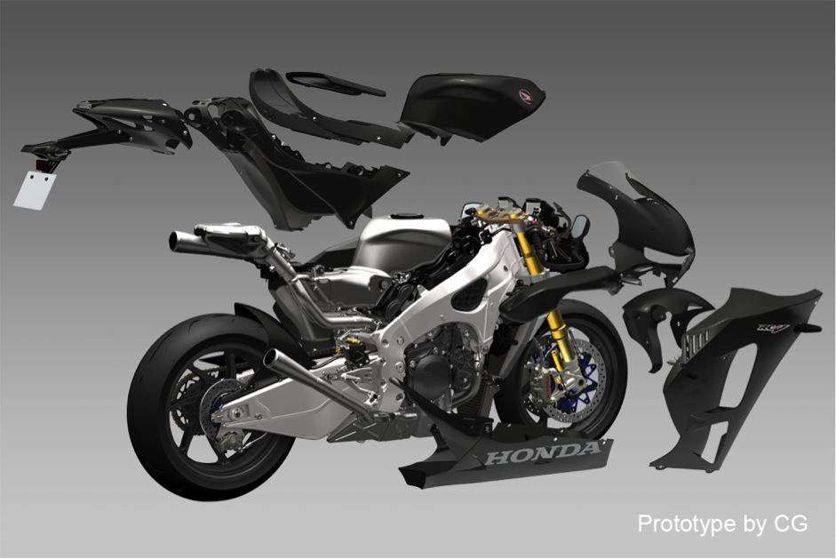
Fairing
For the fairing of the RC213V, simulations and wind tunnel tests were repeatedly conducted in pursuit of a shape that matches the build of the factory team riders competing in races. While maintaining protection performance, the minimized frontal projected area having a shape with very little unevenness has reduced air resistance, helping increase maximum speed. Decreasing the lateral area of the parts that are far from the center of gravity and reducing the moment of inertia have also contributed to nimble handling. Regarding the material for the fairing, pre-preg Carbon Fiber Reinforced Plastics (CFRP) is used for achieving weight reduction and securing the necessary rigidity. After hardening through the autoclave process, terminal processing and drilling are finished by hand. The thickness of each area is changed according to the stack count of carbon fibers, in order to ensure the optimum strength and rigidity for each member while also achieving weight reduction.
The fairing of the RC213V-S also uses the same shape, material and processing method as for the RC213V. The shape around the handlebars has been optimized to ensure sufficient steering angles, in view of the practical characteristics needed in public road riding. For specifications of the external appearance, a tricolor design type or an unpainted CFRP type are available.
Fairing configuration diagram
Seat cowl
Doing away with any seat rail, the RC213V uses a monocoque structure seat cowl made of CFRP, securing the necessary strength while also achieving weight reduction. Without the space restrictions of a seat rail, there is more freedom for the fuel tank shape, and the configuration also helps minimize any change in the center of gravity due to a decrease in the amount of fuel carried, while securing the needed tank capacity.
The RC213V-S also adopts this seat cowl of the same specifications as the RC213V.
Rearview mirrors
The RC213V-S is equipped with rearview mirrors, with riding on public roads as its premise. Mounting the rearview mirrors on the tips of handlebar lever guards has rendered a rearview mirror base on the upper cowl stay unnecessary. With this setting, installing the upper cowl with the same specifications as for the RC213V is possible for the RC213V-S.
Power unit overview
The power unit of the RC213V was developed with the purpose of “creating a power unit for the vehicle with the potential of winning MotoGP races.” To this end, the following two key goals were established.
- Supply high output that matches the speed range in MotoGP racing.
- Create a compact unit that can be installed on frame dimensions equivalent to those of the 800cc RC212V.
To achieve these goals in full compliance with the MotoGP regulations, the RC213V adopted a 90° V4 1,000cc engine. Use of the 360° crank phase angle led to excellent exhaust pulsations resulting from the combustion intervals, which increased charging efficiency to successfully achieve a high power output. In order to make the most of the high power output and to lower the friction, a 90° V4 engine was used, which resulted in less mechanical loss with no balancer necessary, fewer crank journals in three places compared to an inline four cylinder requiring crank journals in 5 places, and less pumping loss thanks to the closed crank pit structure.
A V4 is also effective for shortening the crankshaft, making it possible to decrease engine width. This helps secure the bank angle and reduce the frontal projected area, helping create a compact engine unit. Also with a V bank angle of 90°, in theory no primary vibrations are generated, making a balancer unnecessary and thus shortening the longitudinal engine length. Furthermore, the three shafts of the crankshaft, main shaft and countershaft forming a triangular configuration in side view helps shorten the longitudinal engine length as well. As a result, while displacement of the engine on the RC213V is 1,000cc, the engine size is equivalent to that of the 800cc RC212V engine. In addition, few secondary vibrations rendered vibration countermeasures unnecessary, which combines with the measures for reducing complete vehicle weight to help achieve thorough mass concentration for enhancing maneuverability to the extreme, while the irregular interval combustion helped improve traction performance.
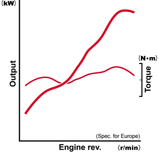
While all these specifications of the RC213V engine are inherited by the power unit of the RC213V-S, the output characteristics that assume riding on public roads have been achieved by changing the engine rpm. To ensure highly precise valve operations well into high speed range, a gear train is used for the cam drive system just as for the RC213V. However, for the valve closing mechanism, the actual use environment for the RC213V-S was taken into account given the riding on public roads, and a switch was made to the coil spring type, because for more practical maintenance characteristics, this setup enables properly maintaining the functions of the RC213V-S. Similarly, the transmission type was changed from the seamless transmission system of the RC213V to a more conventional system.
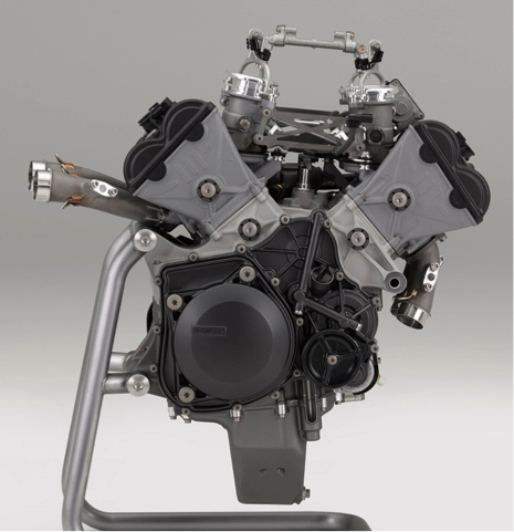
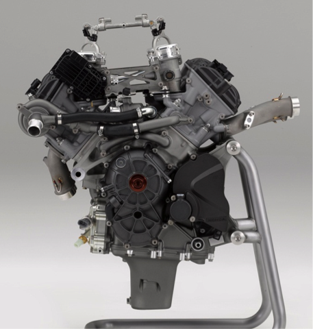
Image diagram of the output characteristics
Crankcase
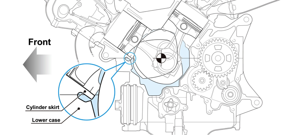
Appropriate measures were taken for the RC213V crankcase to deal with the high output, while also aiming for lower friction and a more compact unit. To accommodate the high power output, a closed deck crankcase with high rigidity was adopted, which limited cylinder deformation due to combustion energy at high rpm. On the inner walls of the cylinder, PNT plating* was applied to reduce sliding friction with the pistons. To reduce engine height for more compactness, the relative position of the cylinder inside the engine was lowered. To achieve this, an oval shape was adopted for the outline of the crankshaft counterweight for downsizing, thus bringing the bottom dead center position of the piston closer to the center of the crankshaft. This resulted in a configuration with the cylinder skirt of the front bank coming into the lower case. With tungsten alloy weights with a large specific gravity press-fit in the crank web, both the unbalance amount and the inertial mass required of crankshaft counterweights are achieved, helping to make the engine compact.
To achieve these specifications of the RC213V, the RC213V-S uses sand mold cast aluminum for the crankcase, because forming complex hollow shapes is possible through this casting method.
* PNT plating: Composite plating using nickel - silicon carbide
Crankcase configuration diagram
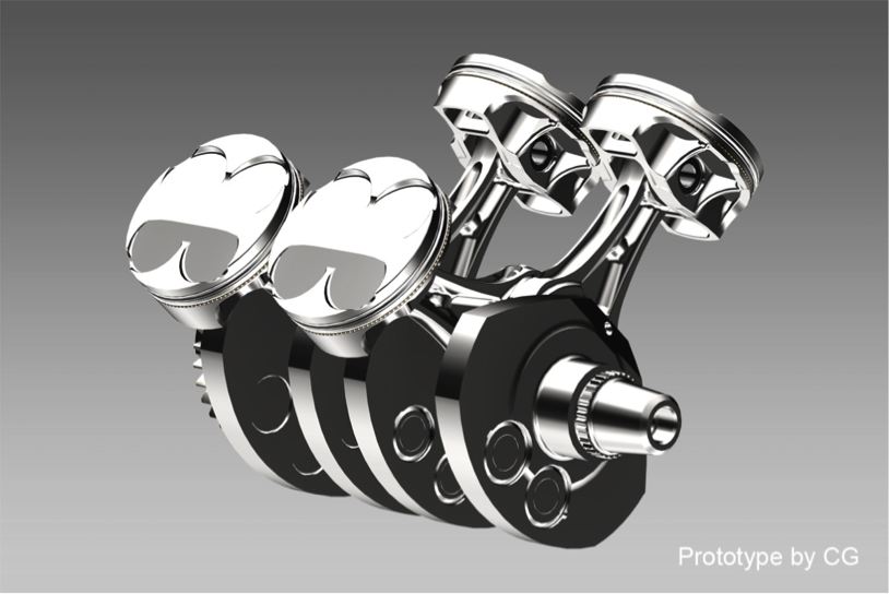
Connecting rod, crankshaft, piston
To deal with the high output, measures were taken to increase rigidity while reducing weight for the reciprocating parts and rotating parts inside the engine of the RC213V.
Applying the same thinking to the RC213V-S, the following specifications were chosen for the reciprocating parts and rotating parts inside its engine.
- Titanium alloy is used for the connecting rod to achieve both high rigidity and weight reduction.
- High-strength alloy is used for the crankshaft to accommodate the high power output when equipped with the Sports Kit.
- Bridge type pistons are used for weight reduction, and to ensure compliance with emissions regulations for use on public roads, the piston ring set has been changed to three rings: the top ring, second ring and oil ring.
Connecting rod, crankshaft, and piston diagram
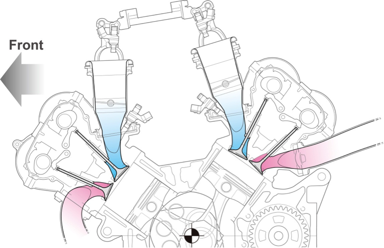
Cylinder head, valve
To increase combustion efficiency, the RC213V uses a straight inlet port that enhances charging efficiency. At the same time, for the purpose of improving throttle response, the inlet port was shortened to limit the inlet port volume. In addition, reducing the valve holding angle for both intake and exhaust limited the surface area of the combustion chamber, helping increase combustion efficiency. To increase the intake and exhaust efficiency, a large valve lift was secured, and a finger follower rocker arm system was adopted to ensure precise valve operations. The RC213V uses lightweight titanium alloy valves with high rigidity.
The RC213V-S adopts the head valve of the RC213V, but for the valve closing mechanism, the pneumatic valve spring system of the RC213V has been switched to a coil spring system, which has ensured valve lift characteristics more suitable for riding on public roads, while ensuring consistent functions through practical maintenance measures.
Cross section of the cylinder head area
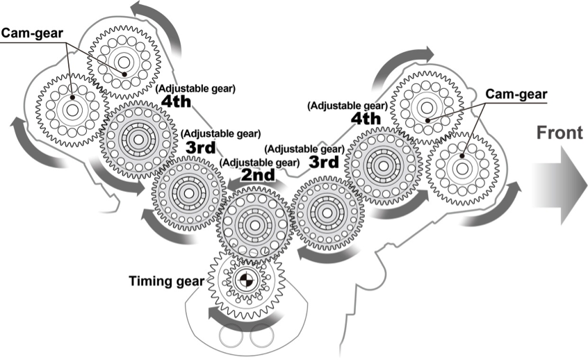
Cam-gear train
For its cam driving mechanism, the RC213V uses a cam-gear train for improving reliability in the high rpm range and decreasing friction for the camshaft drive. The cam-gear consists of a total of 10 gears in the front and rear cylinders. The gear backlash adjustment is ensured by selecting from a multiple number and coupling them for each of the gears.
In contrast, the RC213V-S adopts an eccentric adjustment mechanism with coaxial cam-gears, enabling backlash adjustments without the need to replace gears.
Cam-gear train – Gear layout drawing
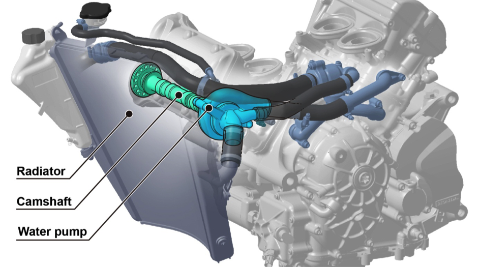
Water pump
To capitalize on the deep bank angle thanks to the shorter crankshafts of a V4 engine, the water pump of the RC213V is positioned in the cylinder head, which secures banking angles for the vehicle body as well as bringing about the following benefits.
- By obtaining from the camshaft the revolving speed appropriate for the driving power to run the water pump, a dedicated driving mechanism such as reduction gears, etc., is no longer necessary, contributing to weight reduction and lower friction.
- The configuration places the radiator and water pump nearer to each other, achieving a shorter water pipe, and the resulting reduction in pipe length and in the amount of cooling water contributed to weight reduction.
The RC213V-S also adopts this same design.
Water pump diagram
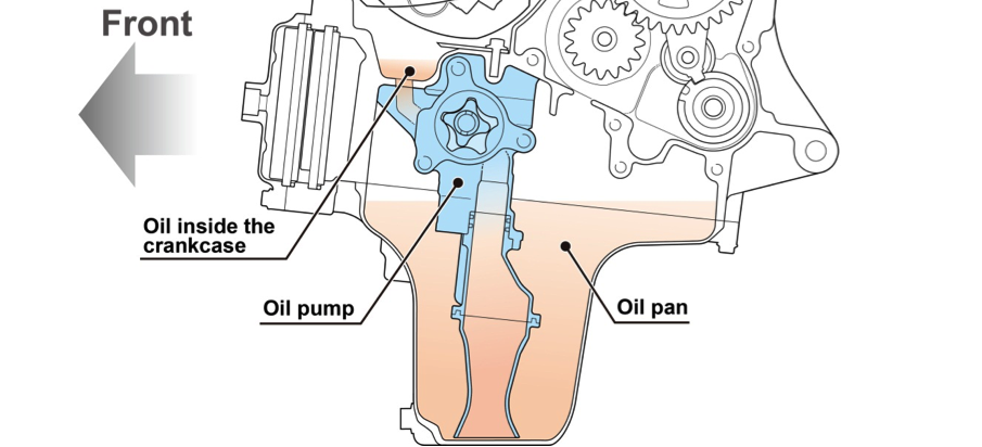
Oil pump
To maintain negative pressures inside the crankcase and reduce pumping loss, the RC213V uses a scavenge pump.
The RC213V-S also uses the scavenge pump.
Oil pump diagram
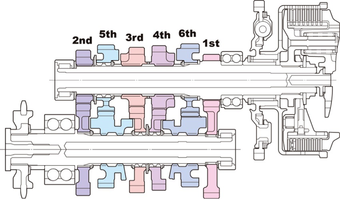
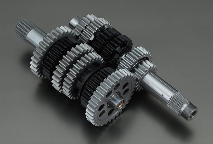
Transmission
For transmission, the RC213V uses a cassette transmission to facilitate inspections and improve the maintenance characteristics.
The RC213V-S adopts the same setup, but instead of the seamless transmission system used on the RC213V, a 6-speed return system that is more conventional for a sports motorcycle has been selected for use on public roads.
To ensure the high strength and precision that will contribute to the accurate gear-shifting changes required of the RC213V-S, wholly machined nickel-chrome molybdenum steel is used as the material for the transmission.
Transmission cross section configuration diagram
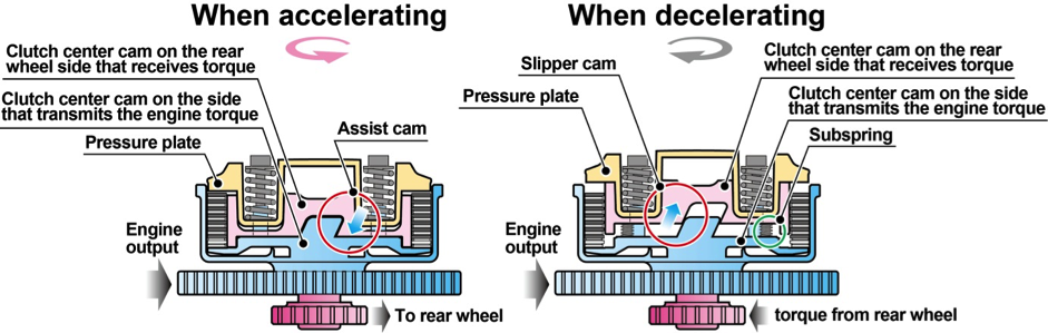
Assist & slipper dry clutch
The RC213V-S adopts the same assist & slipper dry clutch as the RC213V.
In addition to the disengagement performance of a dry clutch, the friction material is heat-resistant and abrasion-resistant sintered material with highly controllable user-friendliness, thus ensuring durability and responsiveness to delicate operations. Use of a hydraulic clutch has reduced friction for the system, ensuring an excellent operation feeling.
The assist & slipper clutch is a clutch system with the assist functions to ensure excellent clutch operation feeling and a light operation load even under rigorous conditions such as at the start of a race, and with slipper functions that contribute to stable vehicle body behavior when abruptly shifting down.
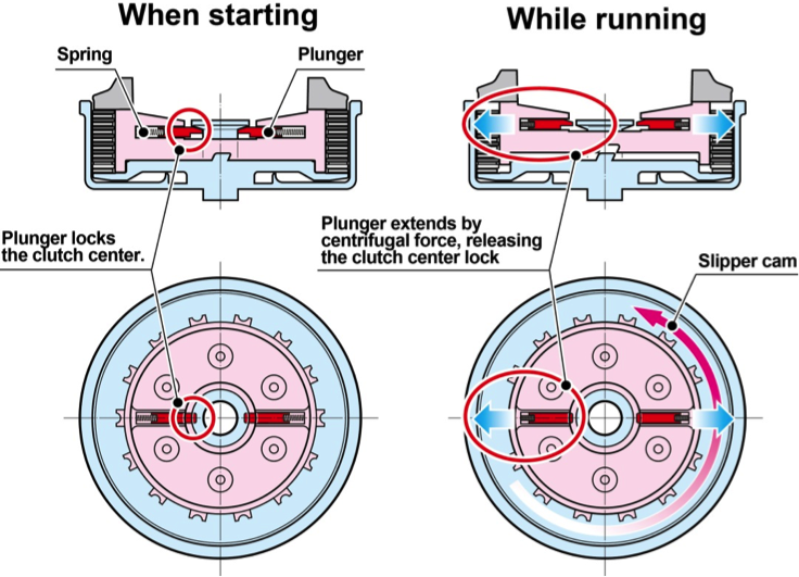
Use of the centrifugal governor system for the slipper cancellation mechanism enables starting the engine from the rear wheel with the engine starter or a push start.
Explanatory diagram of the assist & slipper clutch mechanism
Explanatory diagram for the slipper cancellation mechanism
Intake system
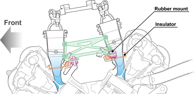
―Insulator with an independent throttle body mount and seal structure
To achieve compactness and high output for the RC213V, the configuration of the engine intake route was optimized by machining the inner surfaces, and the suction pipe length was shortened.
To establish a structure for shortened suction pipe length, the insulator connecting the engine and the throttle body has only a seal structure, and the mount structure supporting the throttle body is separate as independent parts.
The insulator as the sealing material is placed in the overlapping area, when the throttle body is inserted in the concave portion of the inlet port. The throttle body is rubber mounted using another member set in another location, and this structure results in a shorter suction pipe length.
The RC213V-S adopts the same structure as for the RC213V.
Diagram of insulator with an independent throttle body mount and seal structure
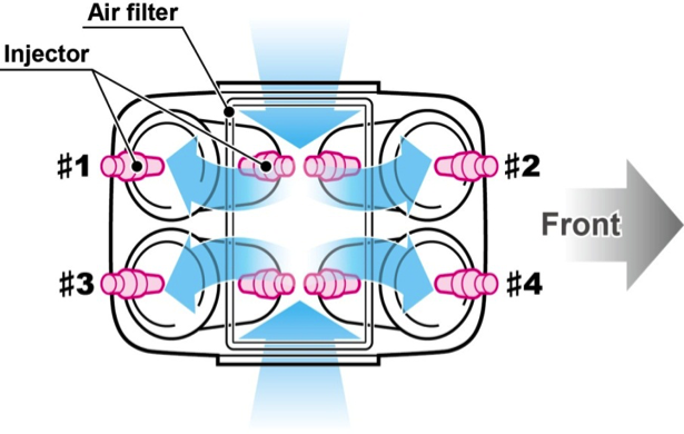
―Upper injector inside the air cleaner
Installed on the RC213V are two injector units per cylinder that supply fuel according to traveling conditions such as the engine rpm and throttle opening, thus optimizing the fuel supply and the timing. To ensure the potential for accommodating the rider’s rigorous demands for output control, the maximum possible volume for the air cleaner case has been secured in a limited space. On the upper part of the throttle body, the upper injector and the fuel delivery pipe are positioned, with this structure contained inside the air cleaner case made of CFRP*.
The RC213V-S also adopts the same layout as for the RC213V. With the aluminum fuel delivery pipe, injector stay, and air funnel wholly machined from aluminum, etc., the necessary volume for the air cleaner case is ensured despite the compact vehicle body, contributing to the excellent output characteristics.
* Pre-preg Carbon Fiber Reinforced Plastic
Injector layout inside the air cleaner
Exhaust system
―Exhaust muffler configuration
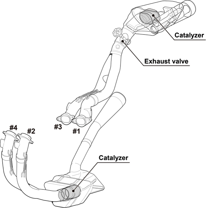
To ensure high output and excellent running performance as well as to reduce air resistance for the RC213V, an independent exhaust muffler is designed for each of the banks of the V4 engine in the front and rear in a compact layout, with most of the mufflers located inside the cowl. Setting the exhaust port for the engine front bank low on the right side of the vehicle body and placing the exhaust port for the engine rear bank right below the rear end of the seat cowl has improved space efficiency, helping make the overall vehicle body more compact. At the exhaust port outlet, the exhaust pipe called an “exhaust collar” that has been processed into a three-dimensional shape is installed for smooth exhaust, contributing to the high power output.
The RC213V-S has also inherited this layout of the RC213V. The expansion chamber for sound attenuation is placed behind the engine oil pan on the engine front bank side, and inside the tail cowl on the engine rear bank side, with a catalyzer set in each of these expansion chambers. At each junction of the exhaust pipe, a gasket is attached, and mounted on the exhaust collar with a three-dimensional shape just as for the RC213V is the air injection system for reducing exhaust emissions. Also for optimum control of the exhaust pressure, variable exhaust valves driven by a servomotor are installed in the front and rear. The variable exhaust valves, the fuel injection quantity and timing, and the ignition timing are comprehensively controlled by an ECU according to riding conditions, thus maintaining the output, noise and exhaust emissions at appropriate levels.
Exhaust muffler configuration diagram
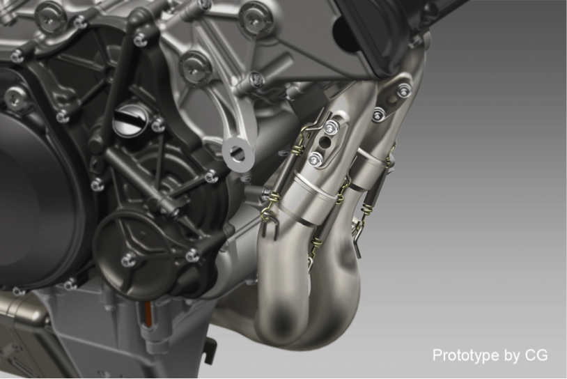
―Securing the exhaust pipe with a spring
Similarly to the RC213V, a spring is used for securing the exhaust pipe for the exhaust muffler of the RC213V-S.
Diagram of the exhaust pipe secured
Electrical control unit
Outline of the control technologies
Just like the RC213V, the RC213V-S is full of control technologies for assisting its outstanding running performance according to riding conditions and the rider’s preference.
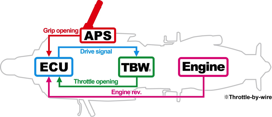
Throttle-by-wire system, grip-integrated accelerator position sensor unit
For throttle control of the RC213V, the accelerator position sensor unit (APS) set at the base of the right handlebar detects grip opening, and the ECU placed inside the tank shelter receives this signal and sends a driving signal to the throttle-by-wire motor, ensuring throttle control fits with the grip opening.
With the return spring and friction generating mechanism inside the APS, the natural operation feeling of a traditional cable type throttle system has been replicated, enabling precise throttle operations without any awkwardness at all.
The RC213V-S adopts the same system as for the RC213.
Throttle-by-wire system configuration diagram
Power selector
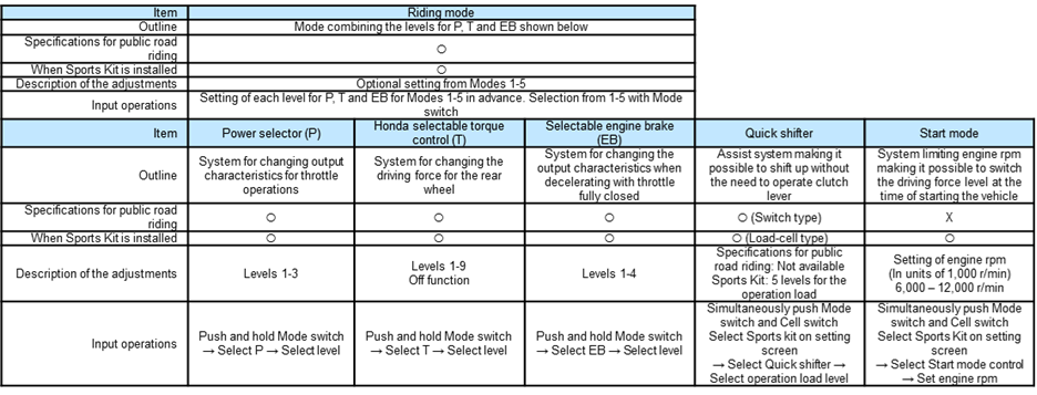
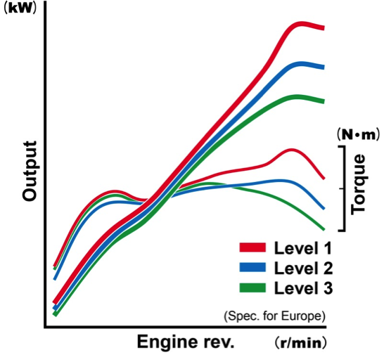
Like the RC213V, the RC213V-S is equipped with the power selector, making it possible to switch among a number of output characteristics in response to throttle operations, according to a wide range of situations and the rider’s preference. It is possible to choose output characteristics from the following three levels available.
Level 1: Possible to reach peak output through all six gear steps
Level 2: Output is controlled for each gear to achieve smoother throttle controllability in acceleration and deceleration
Level 3: With Level 2 as the basis, changes made in the control values set for achieving even smoother throttle controllability in acceleration and deceleration
The selector is operated as follows. Press and hold the Mode switch on the left handlebar and select “P” in the left bottom area of the meter. Then operate the same switch to choose from the Levels 1 to 3. When the P display stops flashing and remains on, this shows that the setting has been completed. Parameter can be chosen freely for each of the riding modes from 1 through 5.
Image diagram of the power selector output characteristics
Honda Selectable Torque Control (HSTC) system
The RC213V-S has adopted the Honda Selectable Torque Control system. Through control of the engine output (torque), a gentler vehicle body behavior is maintained, helping ensure that vehicle body behavior remains within the range easily controllable by the rider.
The Honda Selectable Torque Control system of the RC213V-S uses two types of sensing functions for vehicle conditions in controlling torque. In one of these functions, vehicle speed sensors set on the front and rear wheels detect their rotating speeds. Based on this information, ECU controls engine output (torque), which mitigates the slip state of the rear wheel and assists in ensuring a gentler vehicle body behavior. The other sensing function is to detect the vehicle roll angle. Placed inside the front cowl, the IMU (Inertial Measurement Unit) detects rotational speed in each of the vehicle roll and yaw directions, and acceleration in each of the longitudinal, lateral and vertical directions. Receiving this information through CAN communication, the ECU calculates the vehicle roll angle and controls engine output (torque), providing assistance to mitigate any excessive slip state in cornering, etc. Applied to this computational logic of ECU for vehicle roll angles are the position detection technologies cultivated through the development of ASIMO, thus achieving the calculation results with small variability.
As for intervention levels available with the Honda Selectable Torque Control system of the RC213V-S, switching among 9 levels and also turning the system OFF is possible according to the rider’s preference. The system is operated as follows. Pressing and holding the Mode switch on the left handlebar, “T” in the left bottom area of the meter should be selected. When operating the Mode switch to choose from Levels 0 to 9, the T display stops flashing and remains on, which shows that the setting has been completed.
Selectable engine brake
Like the RC213V, the RC213V-S has engine brake control functions, enabling the rider to switch the engine brake characteristics when the throttle is fully closed, in accordance with wide-ranging situations and the rider’s preference. It is possible to choose from 4 levels, from EB Level 1, when the engine brake applied is the strongest, to EB Level 4. For control, while pressing and holding the Mode switch on the left handlebar, “EB” in the left bottom area of the meter should be selected. When operating the Mode switch to choose from EB Levels 1 to 4, the EB display stops flashing and remains on, which shows that the setting has been completed.
Riding modes
The RC213V-S allows for setting the Riding mode by selecting from 5 Riding modes. It is possible to freely choose and combine values for each of the following parameters (P: Power; T: Honda Selectable Torque Control; EB: Engine brake).
Quick Shifter
Just like the RC213V, the RC213V-S has adopted the Quick Shifter, which is a mechanism that allows shifting up just by operating the shift pedal. With clutch and throttle operations when shifting up now made unnecessary, more pleasant riding is possible. A switch incorporated into the shift rod area detects shift pedal operations and controls fuel injection quantity and ignition timing, making it possible to shift up.
Modes displayed on the meter
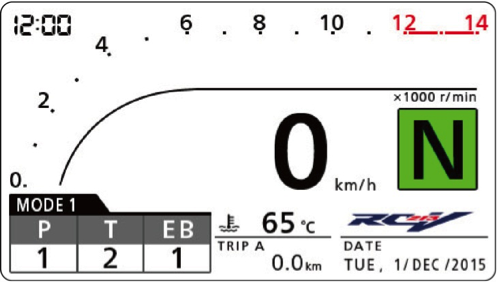
Installed on the RC213V is a multi-functional dot matrix meter with a large screen, which displays only the information necessary at the time of racing. In contrast, taking into account the use on public roads, the RC213V-S has adopted a TFT liquid crystal display meter, in full color for the first time on a Honda motorcycle, which is capable of displaying quite a lot of information. Visibility is enhanced by a backlight with maximum luminous intensity of 1000 cd, which automatically modulates its light linked with the current brightness in the surroundings. Assuming the need for different kinds of information according to riding situation, it is possible to switch among the three modes of meter screen display, which are the Street, Circuit and Mechanic modes providing the necessary information.
For switching among the display of different screens on the transitioning Setting screen, the Select switch and Mode switch on the left handlebar should be pushed and held at the same time.
―The information displayed in Street mode
Power selector
Shift up indicator <5 white LED indicators placed in a row in the upper side of the screen. When reaching the engine rpm set by the rider, they come on and flash to urge shifting up>
Maintenance timing, malfunction notice, warning and other information is displayed at the necessary timing on the twin-trip meter, on the onboard computer and on the meters for vehicle speed, tachometer, gear position, water temperature and mileage.
* Onboard computer
Only in Street mode, the following information is displayed in the bottom right of the screen.
By selecting an item, the numerical value is displayed: Digital tachometer, Instantaneous fuel consumption, Average fuel consumption, Average vehicle speed after the ignition on, Elapsed time after the ignition on, Calendar, Remaining fuel after RES coming on, Distance to empty after RES coming on.
Street mode
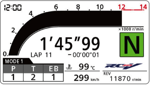
―The information displayed in Circuit mode
The following information is added to the information of Street mode: Lap time, Number of laps, Difference from the best lap.
Circuit mode
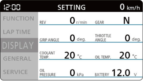
―The information displayed in Mechanic mode
Numerical values for Digital tachometer, Gear position, Grip opening, Throttle opening, Water temperature, Oil temperature, Oil pressure and Battery voltage are displayed.
Mechanic mode
―Various warning messages
The following warning messages are displayed. Side stand warning (displayed if side stand is out, including when the vehicle is stopped), reserve display (Linked to RES indicator of the fuel gauge), low oil temperature warning (when on, rev limit display of the tachometer linked to oil temperature), trouble with Honda Smart Key, low battery voltage for Honda Smart Key.
―Display of the maintenance timing
Maintenance timing for the following items is displayed. General inspection and maintenance, engine oil change, and clutch inspection. When the mileage until change or the inspection timing draws near, the distance until and the timing (month, year) for the exchange or inspection are displayed in the multi-information section in the bottom right of the screen.
―Malfunction notice
On the RC213V-S, a malfunction is notified not only by the warning lamp coming on, but also by the description displayed in the Multi-information section in the bottom right of the screen, so that the rider can know machine conditions in more detail.
Based on the 44 types of malfunction codes as issued by the ECU, the area of malfunction is displayed as follows, as classified into 9 major categories: Engine sensor, injector, ECU, exhaust actuator, gear sensor, speed sensor, throttle-by-wire sensor, throttle-by-wire actuator and CAN communication lines. In addition, the RC213V-S comes with the functions to notify the area of malfunction when equipped with the Sports Kit.
Lights
The RC213V-S adopts LED light sources for all the lights necessary for riding on public roads (Headlight, Taillight and stop lamp, Turn signals, License plate lamp), ensuring power saving and lightweight and compact lights.
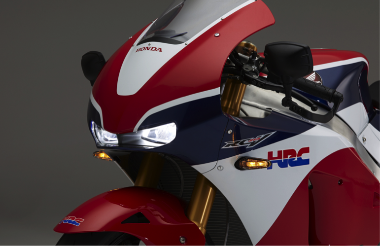
―Headlight
The RC213V-S uses a high-intensity LED package headlight, with total luminous flux of 1000 lm (lumens) for 1 LED. While integrated inside the upper cowl duct to ensure a shape not spoiling the impression of the RC213V, the headlight successfully achieves the necessary and sufficient light distribution performance for riding on public roads.
LED headlight
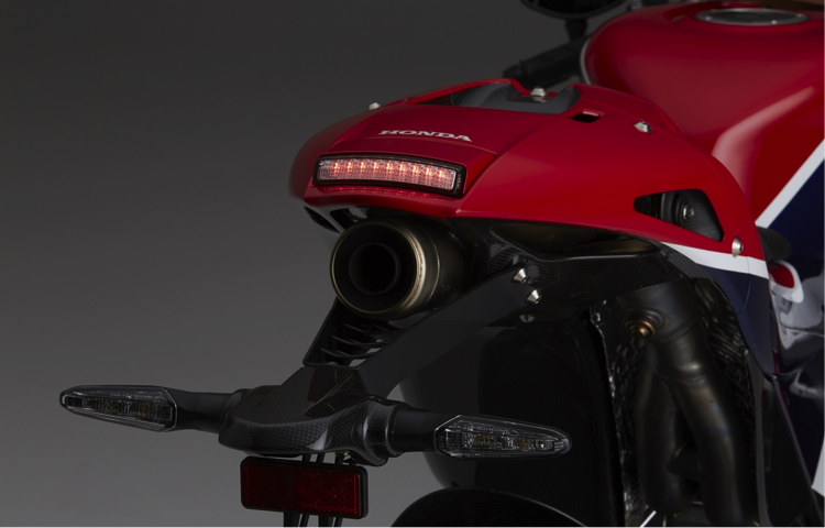
―Taillight
The RC213V-S has a taillight unit with simple shapes, a lightweight and compact design not spoiling the impression of the RC213V, and the LED taillight and stop lamp achieve the necessary light distribution performance for riding on public roads. (Except for the North American model)
LED taillight and stop lamp
―Rear light cluster module
Modularization of the installation area for rear turn signals, license plate lamp and the license plate has been achieved for the RC213V-S, by considering the possibility of riding on a racing circuit. For weight reduction, aluminum material was used for the stay portion, and the louver and housing are made of CFRP.
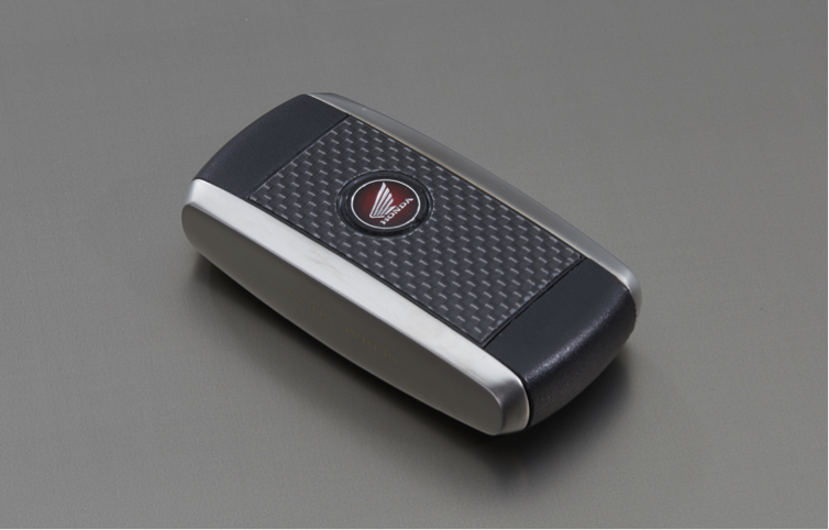
Honda Smart Key
To instantaneously turn the ignition on with one move, without the need to insert and turn a key, the Honda Smart Key system has been adopted instead of a conventional mechanical key. When the vehicle and the key match each other through electronic authentication, turning the ignition on becomes possible. This has also made it possible to do away with any key cylinder around the top bridge, helping achieve a cockpit view similar to that of the RC213V.
At the same time, the handlebar locking mechanism and the opening and closing of the fuel lid are performed with a mechanical key, to achieve weight reduction. With a structure allowing for storage of the mechanical key for handlebar locking and opening and closing the fuel lid inside the Honda Smart Key unit, there is no hassle of having to carry around these keys separately. The surface of the Honda Smart Key is made of CFRP, while aluminum is used for the side area, creating a high-grade appearance overall.
Coloring
For coloring of the RC213V-S, one color design is offered; an original color for the RC213V-S, with the tricolor design based on tradition and heritage.
An unpainted CFRP type is also available, however, based on the premise of owners freely choosing the color(s) of their preference.
With each of the RC213V-S being a machine for private ownership and use, an appearance quality exceeding that of the RC213V is aimed for, and coloring is carried out by full-time experts in all processes. High-quality finish has been accomplished by using the same methods as for factory team machines, including surface preparation work arranging the CFRP surfaces, meticulous masking through manual procedures, and masking applied not only to the front but also on the backside of the cowl for weight reduction.
The tricolor design represents the corporate colors of Honda Racing Corporation (HRC) since its founding in 1982, as well as the typical colors on Honda’s factory team machines. Of the three colors, Red symbolizes the passion and determination of people putting a lot on the line for victory, Blue stands for theory-based technological strengths, and White symbolizes all the customers who love motor sports. As well as showing the pedigree of the RC213V-S, the tricolor design embodies our respect toward all customers and the continuous and ongoing glorious achievements of everyone associated with HRC. A motif of red circles symbolizing the rising sun are placed on the sides of the RC213V-S as proof of the manufacturer’s passion and the challenging spirit of the R&D people who carry on the Japanese tradition of sophisticated manufacturing with careful attention to fine details. As for the red color selected for use here, it is a fluorescent color mixed and formed as a dedicated new color worthy of the RC213V-S, after a review of the more than 350 red and red-tinged paint colors that Honda has used on its motorcycle models until now.

Sports kit
The RC213V-S was designed with riding on public roads as the premise, but available as an option is the Sports Kit exclusively for racing that assumes riding on closed circuits, such as racing circuits. Installing the Sports Kit, removing the lights and other procedures can be handled by a designated dealer with exclusive tools for the RC213V-S.
Sports Kit: Items related to the power unit (All for use exclusively on a closed circuit)
―ECU
ECU with the setting mainly for the installation of the front ram duct and exhaust system-related Sports Kit items, for bringing out more power performance necessary in circuit riding. With installation of the Sports Kit as the premise, also accommodating a change for the normal and inverse shift patterns, setting of the operation load of the load-cell type Quick Shifter, change in the number of sprocket teeth, change in the outer diameter of a tire, and Start mode control.
In stopped state, simultaneously pushing both the Start switch and the Select switch activates Start mode control, limiting engine rpm to the level set in advance (6,000-12,000 r/min). Then the rider can turn the throttle grip to full throttle and focus on clutch operations for the start of a race.
―Front ram duct
With the RC213V, airflows are brought in from the upper cowl section with the highest pressure and supplied to the engine for enhancing acceleration performance and increasing maximum speed, providing high ram pressure effects. With the RC213V-S also, after removal of the headlight for circuit riding, connecting the front ram duct to the upper cowl results in ram pressure effects similar to those of the RC213V. Made of CFRP.
―Exhaust muffler
Used as a set with other Sports Kit items. With the same arrangement as the RC213V, with no catalyzer or variable exhaust valve installed. Made of titanium and lighter by about 4.8 kg than the standard muffler of the RC213V-S.
―AI joint cover set
Used as a set with the exhaust muffler of the Sports Kit. When exhaust air injection piping is removed for circuit riding, installed in place of the removed piping. Set comprising the plate and gasket for preventing exhaust gas leakage, and the tube with a plug for filling the hose joint of the air cleaner cover.
―Spark plug
The spark plugs with optimum ignition characteristics and heat range, in line with fuel injection and ignition mapping to achieve high rpm and output with installation of the Sports Kit.
Other items related to sport riding: Exclusively for use on a closed circuit
―Load-cell type Quick Shifter
The shift input detection unit of the Quick Shifter is changed from the switch type for public road riding specifications to the load-cell (load sensor) type, which is the same type as the one on the RC213V. This makes it possible to detect the direction of the force applied to the shift rod when operating the gear shifter, so accommodating both the normal and inverse shift patterns becomes possible. Because detection of the magnitude of the force is also possible, the shift operation load becomes adjustable to 5 levels (with 2 higher and lower levels from the standard position). Making an adjustment to a load level of preference is possible in this way.
―Inverse gear-shifting pattern drum
Gear shifting in the same pattern as the RC213V is possible. Many racing vehicles have the specifications with an inverse gear-shifting pattern compared to ordinary vehicles for public road riding. Rather than lifting the pedal for shifting up at a corner exit, etc., stepping on the pedal instead reduces the loss of time in shifting operations, so this shifting pattern is common in racing. The RC213V-S has adopted the same system of changing the shift drum as the RC213V.
―Data logger set
Vehicle speed, engine rpm, grip opening, and other data recorded in real time while riding are combined with GPS coordinate data, which enables confirmation of how the rider rode the motorcycle, when and where.
The data is recorded in the supplied USB memory, and analysis is started after connecting the USB memory with recorded data to a Windows personal computer with a dedicated analysis software program installed. Information is displayed according to Honda’s unique design for the analysis screen, enabling analysis of riding data with simple operations.
―Rear link connecting rod
Same structure as for the RC213V. Functions to change the total length of the connecting rod with the adjustment bolts, for adjusting vehicle height. Possible to adjust vehicle height by about 30 mm based on tire outer diameter and the rider’s preference.
―Front brake pad
Brake pad with high μ values using exclusive friction material for racing. Made by Brembo
S.p.A.
―Remote control unit for the front brake lever
Possible to adjust as necessary any change in play of the lever while riding on a circuit. Made by Brembo S.p.A.
―Thermostat
Compared to 82˚C in the specifications for public road riding, the valve cracking temperature is set at a lower temperature of 62˚C.
―Sprocket set
In response to the substantial increase in engine speed when riding on a circuit, the 15, 16, and 17t drive sprockets have been coupled with 40, 41, 42, 43, 44 and 45t driven sprockets, making it possible to set the ratio according to the speed range in each circuit and the rider’s preference.
―Clutch guard made of CFRP
Open type made of CFRP just like the RC213V is adopted, which achieves weight reduction and ensures the clutch cooling performance needed when riding on a circuit.
―Front cowl undercover
Specifications with no holes either for horns or handlebar locks, because it is installed after the removal of horns and handlebar.
―Plugs for filling the front turn signal holes
Used for filling the mounting holes after the removal of front turn signals. Made of CFRP.
―Seat back rubber
The RC213V uses the seat back rubber of a shape matching the build and riding style of each rider.
Assuming the needs based on the rider’s build and riding style for the RC213V-S as well, it is possible to mount a rubber part with the same shape as the one on the RC213V.
― Lower cowl drain cap
Due to racing regulations, it is necessary for the RC213V to plug the lower cowl drain hole when riding in sunny weather. This has been inherited by the RC213V-S.
―Wiring kit
Set comprising the watertight caps for protecting connectors that become necessary after removal of the safety-related and electrical parts when riding on a circuit, coupler stay, and tie-wrap parts for fixing to the frame.
Items related to storage
―Front and rear maintenance stands
Maintenance stand made of stainless steel for holding and storing the vehicle in upright position. Designed exclusively for the model for both the front and rear.
―Indoor vehicle cover
Dedicated vehicle cover with storage indoors as the premise. Use of elastic material with raised fabric on the inside. Adoption of a graphic design exclusively for the RC213V-S.


